Pt100 Wiring Methods – 2, 3 or 4 wire?

The wiring of a Pt100 temperature sensor is different to other temperature sensors, in particular thermocouples. It is important to get the wiring of your sensor correct otherwise the measuring instrument may give an incorrect reading or no reading at all.

Conductor material

Cables used for connecting a Pt100 sensor usually have copper-based conductors. In our own sensors, we use plated copper; either tin, silver or nickel-plated depending on the temperature range required. It is however permissible to use plain copper.

For very high temperatures we use Nickel-based cables. Note that the resistance of Nickel is about 5 times that of copper and therefore you should always use a 3 or 4 wire connection system (see below).

The conductor size does not need to be very large. For example, there is no need to use power cable, instrument cable is sufficient. We usually use 7/0.2mm, 24AWG stranded conductors in our own sensors, even with cable lengths of many metres without issue. Of course, it is possible to use a large cable for very long cable lengths but this usually just adds unnecessary cost for shorter runs. For long cable runs, we recommend using a temperature transmitter instead.

learn how to calibrate a Pt100 temperature sensor

Pt100 sensor

calibration

Cable insulation

The type of cable you choose to make the connection between the sensor and the measuring instrument will be determined by the operating conditions of the process. Many sensors we supply have a flying cable which is connected directly to the instrument. This cable is carefully selected in order to meet both the temperature requirements and also other environmental aspects of the application. This could include chemical resistance or water protection.

We generally use cables which have one of four types of insulation as follows:-

PVC is the insulation of choice for almost any cable we see around us in our day-to-day lives. Everything from mains cable through to leads on headphones and mobile phones are invariably PVC. In general, PVC is not a very commonly used cable for many temperature applications due to its limited operating range. Standard PVC is only suitable for use in the range -10 to +70°C. A high-temperature version more commonly used in this industry extends the upper limit to 105°C. There are still plenty of applications that fall within this range and if the application permits the use of PVC then it is the lowest cost option.

If flexibility is required, then silicone rubber is the best choice. Any cable which uses silicone rubber is more flexible than almost any other kind plus it has a very useful operating temperature of -60 to +180°C. Special versions can be made to operate to 240°C making it a viable alternative to more expensive Teflon based products.

Silicone rubber is an excellent material to bond to and it is the material of choice for probes which are required to be moisture proof.

Probably the most versatile cable used in temperature sensor manufacturing, PTFE and more often PFA are used to deal with a wide range of application requirements. PTFE is a tape insulation which is wrapped onto the cable and sintered whilst PFA is an extruded form. These materials form part of a group of materials called Fluoropolymers denoting the use of Fluorine in the composition of the material. Others include FEP, ETFE (Tefzel) and FPM/FKM (Viton).

The operating range for these materials is from -268°C (5K, -450°F) and up to +250°C. Notably, the material retains good flexibility down to -75°C but below this we recommend the cable is used statically.

As well as a wide temperature range, the materials are well known for being practically chemically inert and they can be used with confidence in the presence of almost any substance without risk of degradation.

The material has an extremely low coefficient of friction (the third lowest of all known materials) and is also extremely hydrophobic. This means it repels water and other substances making it extremely difficult to bond to. Whilst we possess the capability to chemically etch fluoropolymer materials prior to potting we recommend selecting other materials where possible for moisture proof assemblies.

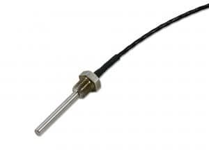
Stainless Steel Armour/Conduit

In some applications it is necessary to provide additional mechanical protection to the cable. The best way of achieving this is to use a stainless steel flexible armour or conduit. This is available in various grades of stainless steel to meet cost and durability requirements. Whilst the armour provides mechanical protection it does not provide any additional waterproofing.

Interested in a Pt100 for your application?

Give us a call at 01628 778688 to discuss your PT100 sensor requirements further.

We offer custom-built temperature sensors for your application. Contact us to find out more.

Pt100 Wiring Diagram

Cable Screening or Shielding

In many applications there is not a need to provide a screen which is grounded. However many of the cables supplied by Process Parameters do have a screen within them. This screening usually takes the form of a plated copper braiding rather than a tape screen as this will withstand a much wider range of temperatures.

Unless requested we do not terminate the screen as a tail which can be earthed but this is available as necessary. From experience, our customers do not experience issues of electrical noise with this type of sensor. If however you have a requirement to have continuous earthing through the complete sensor this can be provided for.

The added advantage of having a braid screen within the cable is the additional mechanical strength this provides. This can be particularly advantageous in applications where there is abrasion of the cable jacket.

Pt100 Sensor Wiring

The basic construction of a Pt100 temperature is based around a precision resistor positioned at the measuring point within the assembly, connected to the measuring instrument by a length of cable. This cable may also include other components such as interconnects, temperature transmitters and so on. In all cases however, there must be some electrical connection between the sensing element and the next component in the system.

Clearly when measuring temperature using a Pt100 RTD sensor we are interested only in the resistance of the sensing element. However any component added to the measuring circuit including the wire or cable used also has its own resistance. This can potentially cause measurement errors if not considered carefully.

Whilst it is perfectly possible to connect a Pt100 using a two-wire connection you should understand that this will introduce measurement errors due to the resistance of the lead wire. This is because the measuring instrument will measure the total resistance of the measuring circuit and not just that of the sensing element itself.

If you consider that the resistance changes per degree Celsius of temperature change is just 0.3851Ω, then by adding in connection wires with a resistance of even just 1Ω would lead to an error of approximately +2.6°C.

Having said that two wire connection is often used and Process Parameters manufactures many sensors with this type of connection. It is often used as a lower cost solution for machine builders who have very short cable lengths. Two wire connection is suited to a few special cases as follows: –

  • Where the application does not have a high demand for accuracy.
  • Where the sensor cable is very short.
  • Where the error is determined by testing and an offset applied to the measuring instrument.

If your application demands do not fall into these then there are standard methods of compensating for the lead resistance.

Pt100 wiring diagram from Process Parameters of a 2 wire connection for a low-cost solution limited accuracy

Pt100 Temperature Sensor Wiring Diagram

The addition of a third wire, connected to one side of the measuring element, helps to compensate for the lead resistance. It is very important that each of the three wires used in the measuring circuit are equal in terms of both conductor size and length. This is because the measured result is averaged and only gives good accuracy where all three wires have the same resistance.

The 3 wire connection specification works by measuring the resistance value through the detector and also taking a second resistance value through the pair of wires joined on one side of the detector. The subtraction of this resistance value from the total gives the resistance value for the measuring element in isolation.

Three wire connection is by far the most common of all wiring types used in Pt100 thermometry. Many instruments utilise this method of connection including temperature transmitters, temperature controllers, panel displays and data loggers and, in many cases, will not operate correctly if a 2 wire system is used.

If using a 4 wire sensor with a 3 wire instrument you can simply ignore the 4th wire and leave it unconnected.

Pt100 wiring diagram of a 3 wire connection - the most common configuration which helps to compensate for lead resistance

For the greatest accuracy, you should choose a four wire Pt100 RTD specification. This measuring system is the only way of fully compensating for all lead resistance in the measuring system, even if each wire has a different resistance.

The measuring system using one pair of wires to carry the excitation current used for the measurement and the second pair is used to measure the resistance of the sensing detector by measuring the voltage drop.

As the 4-wire connection method fully compensates for all lead resistance we strongly recommend that this is used when using a high specification of Pt100 such as 1/5 or 1/10 DIN tolerance. We believe it is a false economy to specify a high tolerance temperature sensor with its associated cost and then use an inferior measuring system. Four wire connection is predominantly used in laboratories and calibration applications and anywhere the highest accuracy is required.

Pt100 wiring diagram from Process Parameters of a 4 wire connection for the greatest accuracy - predominantly used in labs

Need a Pt100 for your application?

Contact us on 01628 778688 to discuss further.

Alternatively, click on the button and fill out our contact form.

Pt100 Thermocouple Wiring

The term “Pt100 Thermocouple” is misleading as there is no such sensor type. The term is a merging of the names of two separate technologies. When specifying a thermocouple or Pt100 it is important to positively identify which sensor you are using as they are not interchangeable.

It is worth pointing out here that in general, a Pt100 will have tails colour coded Red and White. Clearly if you have three or four tails then the sensor is clearly a Pt100 of either a 3 wire or 4 wire connection. However if the sensor has two tails, one red and one white, can you definitely be sure it is a Pt100?

Unfortunately, the answer is not necessarily “yes”. Many sensor manufacturers will use the same 2 core cable for thermistors as they use for Pt100’s. Also some thermocouple types are identified by red and white tails, namely Type J when using American ANSI colour coding. Compensating cable for type R and S also has red and white tails when colour coded to the German DIN standard but is less likely to cause confusion due to the type of applications this is suited to.

To positively identify a sensor you should look at other methods of testing where there is any doubt.

Pt100 Transmitter Wiring

Another source of confusion regarding the wiring of Pt100 temperature sensors is when there is a temperature transmitter included with the measuring system. You need to check the wiring instructions for the type of transmitter you are using but in general they can be summarised as follows:-

Regardless of whether these are in head transmitter or DIN Rail transmitters you should find two sets of connections. One is labelled “Input” and the other set are labelled “Output”.

The input side will generally have three terminals for a 3 wire sensor input or less commonly four terminals for a 4 wire connection. You should follow the wiring diagram ensuring you place the single white wire (for 3 wire) on one side of the circuit and the two red wires on the other.

The output will normally only have two terminals as a 4-20mA device will almost certainly be loop powered. In other words, the 2 wires connected to the output provide the power supply in but also carry the mA signal out.

These are less common in the temperature industry but do exist and differ only in that the output side of the transmitter will have three terminals instead of two. This is because a single pair of conductor cannot provide both power in and signal output. The three terminals will be labelled Power +ve, Signal -ve and Ground (or similar. Note a common ground for both power and signal).

More about Pt100 Sensors